
Resource
Center
Welcome to the Hamar Laser Resource Center; your one stop for videos, downloads, case studies and more. With over 50 years of laser alignment experience our knowledge is vast.
Choose Resource
Hamar Laser Demo Videos
Our channel for demo videos, tips and system specific video bytes.
Alignment Systems for Geometry – Other Videos
L-743 3D Video – Part 5 – Table Flatness Check with Plane5
L-743 Triple Scan® Laser – How to Check Guideway Flatness & Parallelism
L-702SP 5-Axis Machine Tool & Spindle Alignment Laser – Part 1 Features and Benefits
Hamar Laser Training Videos
Our channel for system specific and support training videos
L-730/L-740 Lasers Alignment Basics: Laser Setup
L-730/L-740 Lasers – Application Training Videos
L-705/L-706/L-708 Bore Lasers – Application Training Videos
L-700 Spindle Laser – How to Align Lathes & Turning Centers
How to Align Lathes & Turning Centers using the L-700 Spindle Laser
L-742/732 Dual Scan® Roll Alignment – Part 1 Features and Specs
A
Arc Second
A measure of angle equal to 1/3600th of a degree or .00006″/ft. (0.005 mm/m)
Axial
Located on, around, or moving along an axis.
Axis of Rotation (AOR)
A straight line about which a body or geometric object rotates. The axis of rotation of a spindle is the centerline around which the chuck or tool holder rotates.
B
Bore Center Error (BCE)
A measure of the offset of a bore’s center from a reference bore’s center.
Buck-In (Bucked-In, Bucking-In)
Aligning a laser plane or laser line to be parallel to a surface, a set of bores, a rotating axis or line of motion being measured. Three reference points on a surface are required to buck-in a laser plane to that surface. Two reference points on a line are needed to buck-in a straight-line laser to a that line (i.e., centerline).
Buttock Line
An aerospace term used to describe a reference line that runs along the length or the longitudinal axis of the aircraft. An aircraft contains several buttock-line sections.
C
Catenary Sag
The curve theoretically formed by a perfectly flexible, uniformly dense cable that is not capable of being stretched further and is suspended from its endpoints. It is a measure of how much the elevation of a cable drops between its 2 endpoints due to gravity.
Colinear
A single, straight line that is lying on and parallel to a second single straight line.
Concentric
Of or denoting circles, arcs, or other shapes which share the same center, the larger often completely surrounding the smaller
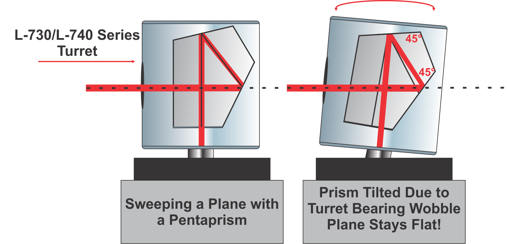
Continuously Rotating Laser Planes
Laser planes that are generated by an automatically rotating spindle containing a pentaprism. Sometimes called a “sweep” laser.
D
Datum
A reference used as a basis for calculating or measuring. See Reference Points.
F
Flashing
A quality problem in plastic parts that occurs when the molds do not contact each other in a parallel manner, which causes excess plastic to build up on the part.
Flatness
The state of having a smooth, even, level horizontal surface without slope, tilt, or curvature.
H
He-Ne Laser
Helium Neon laser is a type of laser that is usually used in interferometry. It is not as spatially stable as diode lasers and usually requires 1 hour warm up.
I
Interferometer
An instrument that measures changes in the linear position (distance) of a machine’s axis. This is accomplished by counting or displaying interference fringes created by a light source of known wavelength. It is typically used to calibrate the scales of machine tools. It can also be used to measure machine geometry but it can only do so 1 axis at a time and cannot be used to re-align the axis since the data does not update in real time.
L
Laser Planes
An automatically rotating laser beam that sweeps a plane of light used to measure surfaces and lines of motion of machine tools. Laser planes measure more alignment parameters with each setup than a laser beam. For example, to measure a surface plate for flatness, it takes 1 setup with a laser plane and 8 setups for a laser beam. Difficult measurements such as rail twist or vertical roll of a machine tool axis are extremely easy to measure with a laser plane but nearly impossible with a laser beam.
Least Squares, Best-Fit Algorithm
The least-squares, best-fit algorithm is a mathematical function that finds the slope of a line (or the X-Y slopes of a plane) that “best fits” a set of data, usually a set of flatness/straightness data. This function is used by our software when we want to measure squareness (or parallelism) of surfaces or lines of motion (axes), since the best way to determine squareness or parallelism between surfaces (or lines of motion) is to compare the slopes of the best-fit lines for each set of data.
Here is the formal definition of the least-squares, best fit function and here is an image showing an example from our Machine-Tool Geometry software showing of a graph of a linear axis flatness data with the least-squares, best-fit line drawn through the data.
Level
Having a flat, smooth surface as characterized by using gravity as a reference. Being on a horizontal plane parallel to earth’s surface
Live/Real Time Data
Target readings displayed on a computer or readout that update automatically as adjustments are made to the point on a machine that is being measured and aligned. This allows the user to watch the machine move into alignment.
N
NORMIN Method
The NORMIN method was developed by Hamar Laser to compensate for laser and/or target mounting errors in bore or spindle work. The word is a contraction of “NORMal and INverted.”
The NORMIN procedure is used to make a laser beam parallel to an axis of rotation in spindle applications or to calculate laser centering errors in bore applications. For spindle applications, it works like this: a laser or fixture holding the laser is placed in a spindle in the normal position (12 o’clock). The laser is turned on and the readings are recorded. Next, the laser is rotated 180°.
O
Offset Centerline
Usually used in roll alignment applications. An offset centerline is a line established to the side of a process mill that is parallel to the machine’s centerline. It is used as a reference to measure roll parallelism.
1 Arc Second
A measure of angle equal to 1/3600th of a degree or 0.00006″/ft. (0.005 mm/M).
Optics
Theodolites, transits, optical borescopes or any other measuring instrument using optical instruments to measure levelness and straightness.
P
Parallelism
2 or more lines or planes, extending in the same direction and everywhere are equidistant from each other. Planes and lines are said to be parallel to each other if they never meet when projected out into infinity.
PDA Display
Used as a target readout in the R-1356-2.4ZB
Pentaprism
A 5-sided prism that accepts a laser beam in one side and projects it at a precise 90. Click here to see an example.
Pitch
As a linear axis travels along the Y axis, the pitch angle of the axis is a measure of how much the bearing or carriage tilts in angle, at a given location, about (around) the X axis (i.e. in the axis perpendicular to the axis of travel), as it traverses along a set of guideways.
Point-and-Shoot Lasers
A type of laser alignment system that does NOT automatically rotate. To take measurements the user has to walk back and forth from the laser to the target to precisely point the laser beam to a target location to get a measurement. Each time the target is moved, the user has to precisely point the laser to the target.
Position Sensing Detector (PSD)
An analog device that uses a piece of silicon to detects the center of energy of the laser beam . The analog signal represents the position of the laser beam and is turned into a digital value by the use of signal processing electronics.
R
Radial
Having or marked by parts radiating from a common center. Moving or directed along a radius and perpendicular to an axial direction.
Reference Points
Points chosen on a surface or in a bore that represent the starting point (reference) from which all other points on the surface or in a bore will be compared. Also referred to as a datum. For bore, spindle and rotating shaft applications 2 reference points are needed to establish a datum. For surfaces, 3 reference points are needed to establish a datum.
Roll
As a linear axis travels along the Y axis, the roll angle of the axis is a measure of how much the bearing or carriage tilts in angle, at a given location, about (around) the Y axis (i.e. in the axis parallel to the axis of travel), as it traverses along a set of guideways.
S
Self-Centering Target
A 2-axis bore target that automatically centers itself in a bore with no moving parts.
Squareness (Perpendicularity)
2 intersecting lines or planes are said to be square to each other if the angle between them is exactly 90 degrees. The measurement of squareness is typically done by using an artifact, such as a piece of granite, that has 2 surfaces that are known to be square to each other to a high degree of accuracy and measuring deviation of a line of motion or surface relative to the artifact.
Another way to measure squareness is to use 2 laser planes (L-732, L-742, L-733, L-743) that are known to be perpendicular to each other and aligning 1 plane to a datum, such as a line of motion on a machine tool, and using the second plane to measure a second line of motion.
Station plane
An aerospace term used to describe a reference plane that runs perpendicular to the buttock lines of the aircraft. An aircraft contains several station planes. They are often also referred to as bulkhead-section planes.
Straightness
The state of having a line that extends continuously in the same direction without curving.
T
Target
A measuring device that detects the position of a laser beam or laser plane. Targets can measure in 1 axis (used with scan planes), 2 axes (used with straight beams to measure H&V center values) and 4 axes (used with straight beams H&V Center, H&V angle)
Target centering error (TCE)
Calculated by adding the normal and inverted readings and dividing the result by 2. TCE is a measure of how far from a bore center the target’s center actually is. Can be used to adjust raw readings to find true bore centering error (BCE).
Top Dead Center Method
Top Dead Center (TDC) method is used when measuring the parallelism or levelness of rolls. With the target facing the laser, the roll is rotated slightly back and forth until the highest point is determined, which is the top dead center of the roll – see here. This should be used when tight tolerances are needed or when it is difficult to determine if the target is near top dead center, usually when measuring vertical rolls.
Can also be called Arc Method or Sweeping Through the Arc Method
W
Waterline
An aerospace term used to describe a horizontal reference plane that runs throughout the aircraft. Many surfaces and interior features are made parallel to this reference plane.
Y
Yaw
As a linear axis travels along the Y axis, the yaw angle of the axis is a measure of how much the bearing or carriage tilts in angle, at a given location, about (around) the Z axis (i.e. in an axis perpendicular to the Y and Z axes), as it traverses along a set of guideways.
We’ve been in business for 51 years which means we have seen it all. During that time, we have aligned almost every application, and as a result, have the widest laser alignment product offering in the marketplace today. Below you will find a very small sample of some of the stories our customers have told us over the years. The list may be small but the number of customers who have successfully profited from using our lasers is too numerous to publish.
- Case Study: Hi-Tech Compressor & Pump Products
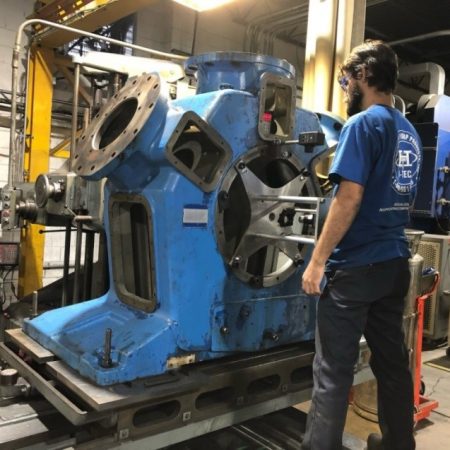 Hi-Tech Compressor and Pump Products, based in Tullytown, Pennsylvania, had just taken on a challenging compressor reconditioning project and was trying to sort out how to QC the alignment. Known for providing expert, responsive service, the company specializes in refurbishing reciprocating compressors and industrial pumps, and has a reputation for high quality work.
Don Weidemann, Hi-Tech’s Director of Quality, had to be certain the tolerances of the compressor bearing bores were on spec, but his customized dial indicator setup was not providing consistent results. The company’s reputation was on the line, the tolerances were very tight and his measurements had to be repeatable and reliable. After careful research, he found the answer in the L-702SP, a new laser alignment system made by Hamar Laser Instruments in Danbury, Connecticut.
Read “Fair and Square: Using lasers to nail critical QC checks on compressors,” published in CompressorTECH2 (digital magazine) and get the article reprint (downloadable PDF).
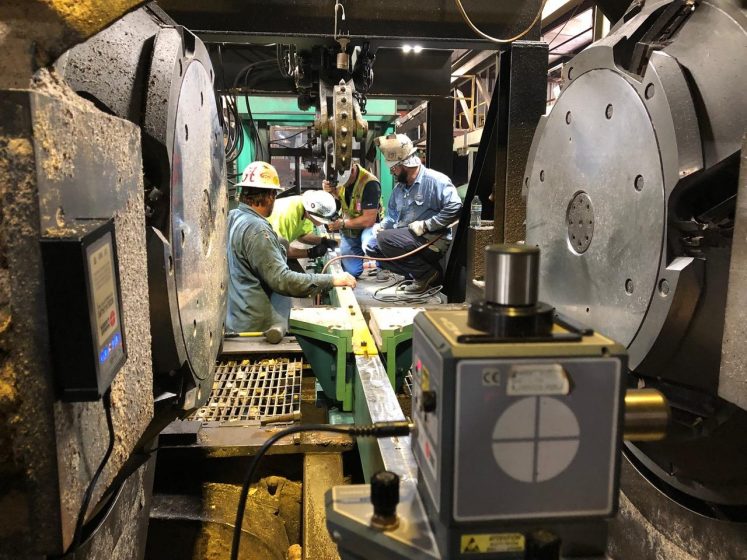
From the get-go, Hi-Tech Compressor and Pump Products worked with Hamar Laser Instruments to develop the procedures to check the large multi-throw compressor frames and align their shaft-bearing bores to a boring mill for re-machining. Hi-Tech used Hamar Laser’s versatile L-702SP Scan Laser with Plumb Beam, along with Hamar’s laser self-centering targets, beam translator, bore adapters and readout.
See the illustrated step-by-step alignment procedures:
“Using Hamar’s L-702SP on Compressors”Want more info?
- Contact us at sales@hamarlaser.com or call 203-730-4600.
- Request a quote / demo.
- Case Study: Laser Alignment in Sawmills
- Lasers Solve Alignment Problems for Dofasco’s Casting Machines
- Alcan Aluminum Switches from Optics to Lasers and Saves $250,000
- Universal Instruments Saves $1.5 Million in Production Costs
- Power Company in Georgia Increases Turbine Efficiency with L-705
- Mark IV Press Runs at Full Speed with No Adjustment Upon Initial Run
- Machine Scrapping Uses Laser Technology to Improve Accuracy
- Lasers Help Reduce Mark IV Press Warm Up Periods
- Laser Borescope Aligned Severely Misaligned 8″ Extruder in 6 Hours
- Laser Borescope Aligned 7 Extruders in 14 Hours!
- L-723* Solves Wrinkling Problem on Mark IV Printing Press
- L-723* Increases Tool Life on Punch Presses
- L-723* Enables High-Scrap-Rate Toshiba CNC to be Certified as a Master CNC
- L-723* Does On-Site QC Checks of Large Parts Before Shipment
- L-700 Spindle Laser Saves One GM Plant $1 Million Annually
- Lorem Ipsum
- Consectetur Adipiscing Elit


- Vestibulum Vel Vehicula Nunc
- Consectetur Adipiscing Elit
- Dolores Sit
- Air Turbulence Effects on Lasers
- HIW - Air Turbulence Effects on Lasers

- HIW - Air Turbulence Effects on Lasers
- Bore Alignment (boring bar)
- Bore Alignment (external)
- Bore Alignment (internal)
- Choosing Reference Points
- Coupling Alignment
- Extruder Alignment
- General Leveling
- Hinge Alignment
- Injection Molding Alignment Lathes
- Lathes
- Machining Centers
- Roll Alignment
- Roll Forming
- Rotary-Dial and Transfer-Line Spindle Alignment
- Saw Mills
- Seat Track Alignment Using the L-733
- StealthAlignment
- Steel Mill - Caster Segment Roll Alignment
- Surface Grinders
- Turbine Alignment
- Twin Barrel Extruder
- Application Features and Benefits
- Basic Leveling Applications L-730/L-740 Flatness Measurement App Note - Features - Rev A.pdf

- Bearing Surface Flatness L-730/L-740 Flatness Measurement App Note - Features - Rev A.pdf
- Blown Film Line L-732/L-742 Dual Scan® Laser Roll Alignment - App Note - Features.pdf
- Boring Bars L-706 Boring-Bar QC Check - App Note - Features - Rev B.pdf
- Continuous Casters L-740-L-743 Caster-Mill Alignment App Note - Features.pdf
- Extruder Laser Alignment Borescope – Single Barrels L-705/L-700 Extruder Alignment - App Note - Features - Rev B.pdf
- Extruder Laser Alignment Borescope – Twin Barrels L-705/L-700 Extruder Alignment - App Note - Features - Rev B.pdf
- Extruders – Single Barrel L-705/L-700 Extruder Alignment - App Note - Features - Rev B.pdf
- Extruders – Twin Barrel L-705/L-700 Extruder Alignment - App Note - Features - Rev B.pdf
- Fabrication Geometries L-730/L-740 Flatness Measurement App Note - Features - Rev A.pdf
- Film Lines L-732/L-742 Dual Scan® Laser Roll Alignment - App Note - Features.pdf
- Gantries and Spar Mills L-743 Triple Scan® Machining Center Alignment - App Note - Features - Rev C.pdf
- General Bore Alignment L-706 General Bore Alignment - App Note - Features.pdf
- Gun Barrels L-703/L-705 Laser Borescope Alignment System for Extruders Brochure - Rev D5.pdf
- Hinge Line Alignment L-705 Hinge-Line Spherical-Bore Alignment - App Note - Features.pdf
- Injection Molding Machines L-732 Dual-Scan® Injection Molding Machine - App Note - Features - Rev-A.pdf
- Large Engine Blocks L-706 Engine Block Bore Alignment App Note - Features.pdf
- Laser Cutting & Water Jet Machines L-743 Triple Scan® Machining Center Alignment - App Note - Features - Rev C.pdf
- Leveling and Flatness Applications L-730/L-740 Flatness Measurement App Note - Features - Rev A.pdf
- Machining Centers L-743 Triple Scan® Machining Center Alignment - App Note - Features - Rev C.pdf
- Med Large CNC Mills, Gantries, Machining Centers, VTLs L-743 Triple Scan® Machining Center Alignment - App Note - Features - Rev C.pdf
- Paper & Converting Machines L-732/L-742 Dual Scan® Laser Roll Alignment - App Note - Features.pdf
- Plastic Extrusion Film Lines L-732/L-742 Dual Scan® Laser Roll Alignment - App Note - Features.pdf
- Presses L-743 Triple Scan® Press Alignment App Note - Features.pdf
- Printing Presses L-732/L-742 Dual Scan® Laser Roll Alignment - App Note - Features.pdf
- Roll Forming Machines L-742 Roll-Forming Machine - App Note - Features.pdf
- Rotary Dial Machines L-700 Transfer-Line/Rotary-Dial Spindle Alignment - App Note - Features.pdf
- Rotary Dial Machines L-703S 4-Axis Lathe & Turning Center Alignment System - How It Works - Rev A2.pdf
- Sawmills L-733/L-743 on Sawmills - How it Works - Rev C.pdf
- Small CNC Machining Centers, Milling Machines and Gantries L-702SP 5-Axis Machine Tool & Spindle Alignment System - How it Works - Part 1 - Laser Setup and Measuring Machining Axes - Rev A.pdf
- Small CNC Machining Centers, Milling Machines and Gantries L-702SP 5-Axis Machine Tool & Spindle Alignment System - How it Works - Parts 2&3 Spindle Alignment and B-Axis Checks- Rev A.pdf
- Small CNC Machining Centers, Multiturn/Millturns and Lathes L-702SP Multi-Purpose Machine Tool Alignment System - How it Works - Part 1 Laser Setup and Measuring Machining Axes Rev A2.pdf
- Small CNC Machining Centers, Multiturn/Millturns and Lathes L-702SP Multi-Purpose Machine Tool Alignment System - How it Works - Part 2 Main Spindle to Sub-Spindle Setup Rev A3.pdf
- Split Joint Flatness Measurement L-706/L-740/S-680 Power Generation App Note - Features.pdf
- Steel Mills L-740-L-743 Caster-Mill Alignment App Note - Features.pdf
- Surface Grinders L-743 Triple Scan® Machining Center Alignment - App Note - Features - Rev C.pdf
- Textile Mills L-732/L-742 Dual Scan® Laser Roll Alignment - App Note - Features.pdf
- Tooling Leveling L-730/L-740 Flatness Measurement App Note - Features - Rev A.pdf
- Transfer Line Spindles L-700 Transfer-Line/Rotary-Dial Spindle Alignment - App Note - Features.pdf
- Turbine Bore Alignment L-706/L-740/S-680 Power Generation App Note - Features.pdf
- Water jet Machines L-743 Triple Scan® Machining Center Alignment - App Note - Features - Rev C.pdf
- Basic Leveling Applications L-730/L-740 Flatness Measurement App Note - Features - Rev A.pdf
- Brochures & Datasheets
- How it Works - Application Step-By-Step Procedures
- Manuals - Laser Systems and Software